Choosing PLC programming support in Melbourne comes down to more than software knowledge. It is whether the team understands your process, your installed platform, and the people who will support the system after startup. If the scope is already clear, our PLC programming Melbourne service covers PLC, SCADA and HMI delivery from P&ID review to site support.
Strong PLC programming rests on understanding the plant well enough to write simple, modular, extendable code that operators and maintenance teams can diagnose under production pressure. That means reading the P&ID, knowing how the pumps and valves behave, proving interlocks, designing recovery paths, choosing the right control language for each task, and staying close to the site after startup.
Metromotion Controls is a control systems integrator based in Mount Waverley that programs process and packaging plant across Melbourne, Victoria and Australia. This article sets out what good PLC programming looks like on a production site, and what plant managers, project engineers and maintenance leads should ask before choosing a programming team.
This post supports our PLC programming Melbourne, SCADA programming Melbourne, HMI programming Melbourne and industrial automation Melbourne pages. Use the PLC page when the immediate need is code, screens, alarms or diagnostics. Use the industrial automation page when the work also includes panels, OT networks, OEM interfaces, commissioning, production data and support after startup.
What PLC programming services actually include
PLC programming is often described as writing ladder logic or configuring a controller. On a manufacturing site the scope is wider. A PLC program turns the plant design into controllable behaviour: it reads instruments, commands pumps and valves, starts and stops drives, enforces permissives, handles alarms, coordinates sequences, presents status to the HMI, and records enough for operators and maintenance to understand what happened. It also has to fit the installed platform, whether Rockwell, Siemens, Schneider, Beckhoff or another supportable controller family.
In practice the work includes:
- Reviewing the P&ID, instrument list, motor list and control philosophy before writing code.
- Mapping equipment into reusable modules: pumps, valves, drives, tanks, heat exchangers and skids.
- Writing sequence logic with named states and clear transitions.
- Building interlocks, permissives, alarms and diagnostics that can be understood on site.
- Integrating HMI, SCADA, historian, recipe and reporting systems where required, including the tags that feed OEE monitoring and production data.
- Testing the normal, fault, restart and manual recovery paths.
- Supporting operators and maintenance after go-live.
The buyer risk is that a program can appear to work on day one and still be expensive to own if it is hard to diagnose, hard to modify, or tied to one programmer's habits. The goal is supportable production, not only a clean startup.
Why process understanding comes before code
Before useful code can be written, the programmer needs to understand what the plant is trying to do and what can go wrong.
For a process plant that means the P&ID, product and transfer paths, tank levels, valve manifolds, pumps, flowmeters, temperature loops, pressure limits, CIP circuits, drains and utilities. For a packaging or machine line it means machine handshakes, accumulation, reject logic, line stops, jam recovery and changeover.
The code should reflect those realities. A pump is not a generic output if it needs dry-run protection, seal water, downstream path proof, start feedback and restart rules. A valve is more than a solenoid when it has open and closed feedback, air-failure behaviour and CIP interaction. A sequence cannot be designed responsibly until the programmer knows what a safe hold, abort and restart look like for the equipment.
This is where fragile programs begin: the software is written around assumed behaviour, then commissioning exposes the real plant. A process-first approach moves those questions earlier, when they are cheaper to solve and easier to test.
Choosing the right PLC language for the job
PLC programming is shaped by IEC 61131-3, the standard that defines the common languages for programmable controllers: ladder diagram, function block diagram, structured text, sequential function chart and instruction list. Platforms implement these differently, but the choice is the same, use the language that makes the logic clearest for the task.
- Ladder diagram suits discrete logic, start conditions, permissives, interlocks and simple motor or valve control. Maintenance technicians can usually read it on a live system, which matters during production support.
- Function block diagram suits continuous control and signal processing, where PID loops, scaling and filtering are easier to follow as a visible signal path.
- Structured text suits sequencing, calculations, recipe handling and conditional logic, where it is compact and readable.
- Sequential function chart suits step-and-transition sequences such as startup routines, batch phases, transfers and CIP cycles.
- Instruction list is deprecated in the standard and should be avoided on new work.
A maintainable program usually uses more than one: discrete device logic in ladder, loop control in function block, sequencing in structured text or SFC. The question is not which language the programmer prefers, but whether the choice helps the site support the logic later.
Modular code that can grow with the plant
Plant code should be organised around the equipment, not as one long list of rungs. Modular structure is what lets a program grow without becoming fragile.
Build the program as equipment modules. A pump, valve, drive, tank, mixer, heat exchanger or skid becomes a reusable block with its own logic, status, permissives, fault handling and interface. When the site adds a pump or a second skid, the team extends a proven pattern instead of editing scattered code. A pump block tested once applies consistently across the plant, and a valve block handles command, feedback, fault, manual mode and alarm the same way every time. Add-on instructions and reusable routines are how a site avoids every device behaving slightly differently.
Keep the sequence layer separate from the device layer. The device module knows how to run a pump safely, the sequence knows when it should run. That separation lets the order of operations change without rewriting the pump logic, and lets the FAT test each layer independently.
Tie tag naming to the P&ID, so a controller tag maps cleanly to the instrument or equipment identifier on the drawing and a site can move from an HMI alarm to a drawing to the PLC logic without guesswork. The same applies to alarm text: use names that mean something to the people at the line.
Sequence logic that can hold, abort and recover
Most plant logic is sequence logic. The site needs equipment to move through defined steps, and to know what happens if the sequence is interrupted. A supportable sequence has named states, explicit transitions and defined behaviour for holds, aborts, faults and restarts.
A transfer sequence, for example, might move through idle, prove path, start pump, prove flow, transfer, hold, stopping and aborted. Each transition has a condition: downstream valve open, tank level above low-low, pump feedback proven, flow above minimum, batch complete or operator stop requested. Each state shows its status on the HMI, so operators can see whether the system is waiting for a valve, a level, a flow condition, an interlock or a reset.
This matters during faults. Written as scattered flags and timers, the plant may not know whether it was filling, heating, transferring or stopping when a fault occurred, which leaves no safe restart except a full reset. Written with explicit states, the program can hold safely, drive equipment to the intended state, show the cause, and resume or abort in a controlled way. Good sequence logic answers the practical questions a site asks under pressure: what state the equipment is in, what it is waiting for, which permissive or interlock is holding it, what happens on stop, and what happens if air, power, flow, level or feedback is lost.
Most Australian sites already have a control platform, and the right team works with that installed base where it is still supportable. A programmer who only recommends the platform they know best can create unnecessary cost and long-term support risk.
Rockwell Automation, programmed in Studio 5000 with the Logix controller family, is common across Australian manufacturing. It uses named, typed tags and supports reusable logic through Add-On Instructions, with FactoryTalk often alongside for HMI, SCADA and historian functions. Siemens, programmed in TIA Portal with the S7-1200 and S7-1500 families, organises logic around function blocks, data blocks and instance data, and is strong where the site already runs Siemens PLCs, HMIs, drives or machine suppliers.
Other platforms can be the right fit. The decision should weigh spares, support contracts, site familiarity, existing code libraries, OEM requirements, lifecycle status and integration needs. For a plant manager the better question is not which platform is best, but which best matches the installed base, staff capability, support model and upgrade path. A platform change can make sense when a controller is obsolete, but that is a legacy PLC migration planned as a PLC and automation upgrade, not a casual programming preference.
Making faults easy for site staff to diagnose
Operators and maintenance teams need code and screens that tell them what is happening. Useful diagnostics start in the PLC and carry through to the HMI. If a pump is held off, the site should see the reason: low tank level, downstream valve not open, drive fault, E-stop active, manual mode, permissive not met or sequence not in the right state. If a sequence is waiting, the active state and waiting condition should be visible.
This affects production time directly. A vague alarm such as "Sequence fault" sends the site hunting. A diagnostic such as "Transfer P-101 waiting: XV-301 open feedback not proven" points maintenance straight at the valve, feedback switch, air supply or wiring. Clear permissive displays also reduce unsafe workarounds, because staff who cannot see why equipment is held are more likely to bypass, force or jog around the condition.
FAT, commissioning and day-to-day support
A PLC program is finished when the site has tested its behaviour, operators understand how to use the system, and support is available when production hits issues.
Factory acceptance testing should cover the normal path and the fault paths, proving every sequence step, transition, permissive, interlock, alarm and restart condition that can reasonably be tested before site, including holds, aborts, manual and automatic modes, and loss of feedback or services. A FAT that only proves the line runs in ideal conditions leaves the real risk for startup.
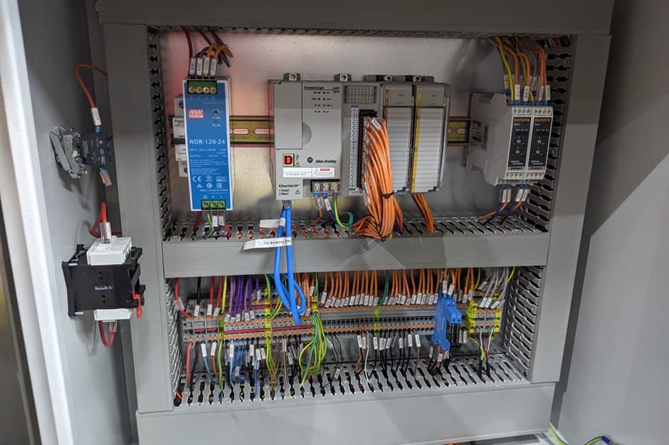
Commissioning confirms the software against real wiring, instruments, drives, valves, pumps and HMI screens, where I/O checks, loop tuning, instrument scaling, alarm verification, sequence dry runs and product trials come together, and where operators start learning what the new screens, alarms, modes and recovery steps mean.
Support after startup is where the program becomes part of day-to-day work, especially through the first production windows, product changes, cleaning cycles and abnormal stops. That can include shift walk-throughs, operator coaching, maintenance fault-find support and minor adjustments after real use. It is part of the engineering, not a formality after installation.
How to choose a PLC programming team in Melbourne
When comparing teams, look past the capability list at how they reduce plant risk after startup. The best early signal is the conversation before they talk about code. A good programmer asks how your process runs, where operators lose time, which faults keep returning, what maintenance struggles to diagnose, and which product changes are painful. A food, beverage or dairy process with CIP, transfers and temperature loops carries different operating pressure from a packaging line or utilities skid, and the right team works to understand those pain points before deciding how the PLC, HMI and diagnostics should behave. Check too for a track record of supporting sites after installation, not only starting them up. That is the standard Metromotion Controls works to across PLC, SCADA and HMI programming, systems integration, industrial automation, commissioning and support for Victorian manufacturing sites.
For a buyer, the cleanest split is scope-based. If the line needs new sequence logic, a SCADA screen change or better fault messages, the commercial fit is PLC, SCADA and HMI programming. If the same job also needs control panel engineering, OT network changes, line handshakes, commissioning planning and ongoing support, it belongs inside the broader industrial automation Melbourne scope so the full control stack is planned together.
Common pitfalls to avoid
The same problems recur on programs that are hard to support, and most are structural rather than syntactic.
- Writing code before understanding the process. If the programmer has not understood the P&ID, operating modes, interlocks and recovery paths, the site finds the gaps during commissioning.
- One monolithic program. Logic written as one long listing rather than equipment modules is hard to read, test and reuse.
- The wrong language for the task. Forcing maths into ladder or sequences into function block produces code that technically works and nobody wants to maintain.
- Implicit state. Sequences built from scattered flags and timers cannot explain where they are or why they are waiting.
- Weak hold and abort handling. Logic that handles only the normal path leaves the plant in an undefined condition when something fails.
- Poor diagnostics. Operators need to see which permissive, interlock, fault or feedback condition is holding the equipment.