1
Scope from the operating constraint
Define the job by the production problem first, whether that is downtime, changeovers, traceability or poor visibility. The constraint shapes the work more than the hardware brand does.
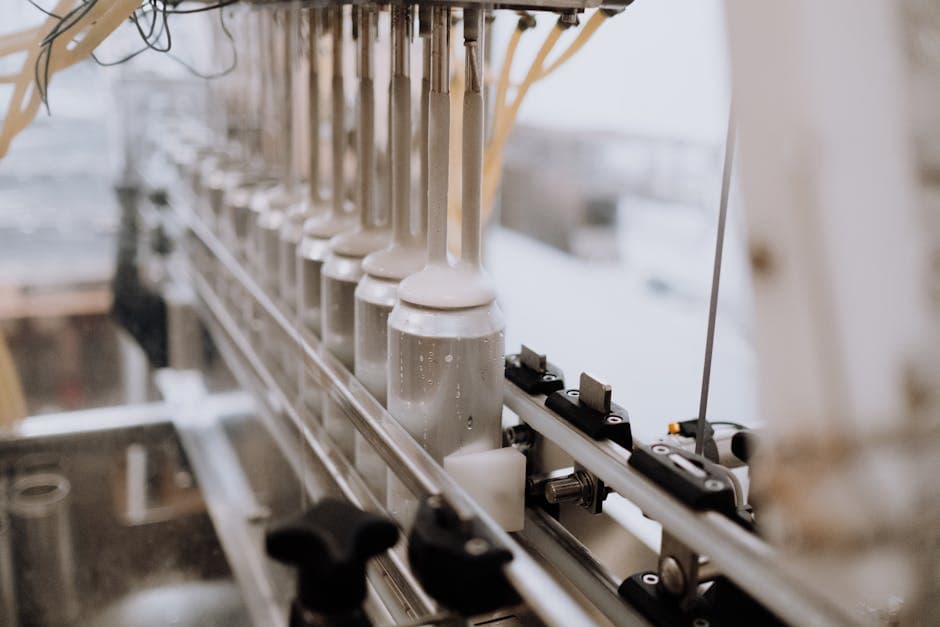
Define the job by the production problem first, whether that is downtime, changeovers, traceability or poor visibility. The constraint shapes the work more than the hardware brand does.
PLC logic, SCADA or HMI, control panels, drives, the OT network and commissioning all interact. Treating them as separate jobs is where most gaps and rework appear.
On an existing plant the installed state rarely matches the drawings. Verifying real I/O, comms paths and interlocks early is what keeps the budget and the outage window honest.
Industrial automation projects in Melbourne and across Victoria are usually justified by a plant problem rather than by a technology wish list. The best starting point is the operating constraint itself, whether that is unplanned downtime, slow changeovers, weak traceability, rising labour load, or limited visibility into how the line is actually performing. The constraint defines the job. It tells you which parts of the control system carry the work and which are secondary, and it gives you a measure to design against and to defend the spend internally.
For delivery support, see industrial automation Melbourne, control systems integrator Melbourne and PLC programming Melbourne. The industrial automation service page is the best starting point when the job spans PLC, SCADA, HMI, control panels, commissioning, support and production data rather than one isolated programming change.
Industrial automation is the use of control systems to run plant and machinery with limited direct human intervention. On a manufacturing site that resolves into a fairly consistent set of layers, and a sound project treats them as one system rather than as separate purchases.
The controller is the centre of it. A programmable logic controller (PLC), or its larger relative the programmable automation controller, reads sensors, runs the control logic, and drives outputs to valves, motors and actuators. Above it sits the operator interface, either a local human-machine interface (HMI) panel or a plant-wide supervisory control and data acquisition (SCADA) system that visualises the process, manages alarms, and records data for reporting and traceability.
Around the controller is the electrical scope. Control panels house the controller, the protection, the power distribution and the field terminations, and they are engineering work in their own right rather than a box to drop hardware into. Motor control runs through variable speed drives and soft starters, which set how pumps, fans and conveyors accelerate and hold speed. Tying it together is the operational technology (OT) network, the industrial Ethernet and fieldbus links that carry data between controllers, drives, instruments and the SCADA layer. The final layer, integration, is where the line connects to upstream and downstream equipment and to higher-level systems such as a manufacturing execution system.
For the controls and panel scope, see PLC, SCADA and HMI programming, control panel engineering and OT networks.
A new line on a clean site and an upgrade to a running plant share a vocabulary, but they are different engineering problems and they need different planning.
Greenfield work starts from a clean sheet. The drawings describe what will be built, the design can be optimised without inherited constraints, and commissioning happens before any production depends on the line. The main risks sit in specification and coordination across disciplines rather than in the unknowns of an existing plant.
Brownfield work modifies a plant that is already producing, and that changes everything about the planning. The constraints are the existing field wiring, the installed I/O, the interlocks with adjacent equipment, and the short shutdown windows available to make changes. The largest single risk on brownfield work is that the installed state does not match the records. Drawings drift over years of small modifications, serial links go undocumented, packaged equipment arrives with its own controller and its own interfaces, and ladder logic gets hand-modified on night shift and never written up. Most of the engineering effort on a brownfield project goes into discovery and into staging the change so the line keeps producing. Where the work involves replacing ageing controllers, the planning overlaps heavily with a dedicated migration, covered in legacy PLC migration in Australia. For upgrade delivery, see automation upgrades.
The control logic is written to an international standard, and knowing it helps when scoping and reviewing a project. IEC 61131-3 defines the programming languages for PLCs, and the major vendor environments align to it. PLCopen maintains the standard and publishes guidance on portable, well-structured code (PLCopen). A well-built application uses each language where it fits:
The practical point for a manufacturer is that the language choice should follow the process: interlocks and machine logic in ladder, loops in function block, sequencing in SFC, and data handling in structured text. That gives an application each part of the team can read and support. For loop work specifically, the tuning matters as much as the language, covered in PID loop tuning for food and dairy.
The order of work decides how much risk a project carries. Buying hardware first and discovering the plant later is the most common way to turn a tidy upgrade into an overrun.
Start with the production constraint and write it down as a measurable target. Then run discovery against the installed plant: verify the real I/O count, the network and serial links, the third-party packaged equipment and its interfaces, and the interlocks with adjacent lines. On a brownfield site, treat the drawing set as a hypothesis to be checked rather than as fact. From an accurate picture of the plant, define the delivery in stages with a clear acceptance sequence and a written cutover plan.
The acceptance sequence is where confidence is built before production depends on the new system:
IEC 62381 provides a recognised framework for structuring and recording factory and site acceptance tests on automation systems (IEC 62381). Working to a recognised structure keeps the test scope, pass criteria and sign-off consistent, which matters most when several parties share responsibility for a cutover. For testing and startup support, see commissioning and systems integration.
The following figures are illustrative engineering numbers used to show how a staging decision is reasoned through, not a real Metromotion Controls or client result.
Consider a packaging line on a Melbourne food plant running an ageing controller, with two adjacent lines that share an interlock at a common accumulation table. The site wants better changeover handling and structured traceability, and it can offer two short shutdown windows of around 10 hours each across consecutive weekends, plus a longer window of about 40 hours over a holiday period.
The first decision is whether to attempt a single full cutover in the long window or to stage the work. A single cutover in the 40 hour window looks attractive because it is one event, but the shared interlock means a fault on the upgraded line during restart can stall both neighbours, and 40 hours leaves little room to recover if discovery has missed something. A staged approach uses the two shorter windows for the work that can be isolated, such as installing the new panel alongside the existing one, pre-wiring the new controller, and proving I/O against a simulator, while the line still runs on the old system. The long window is then reserved for the cutover itself, with the riskiest work already de-risked.
A rough sizing illustrates the trade. Suppose discovery finds about 180 field I/O points, roughly 30 of them in the cross-line interlock. Re-terminating all 180 cold during a single window might consume 12 to 16 hours before any testing, most of the long window gone. Staging the field work and reserving the long window for the controller swap, the interlock proving and the sequenced restart leaves a realistic margin for a go or no-go decision and a rollback if a check fails. The reasoning, not the numbers, is the transferable part: stage the work to keep each window small and each rollback realistic.
The integrator decision shapes the project more than the brand of PLC. A few criteria separate a sound choice from a risky one.
| Criterion | What good looks like |
|---|---|
| Scoping approach | Scopes from your production constraint, not from a preferred hardware list |
| Process understanding | Reads the line as a process, not only as I/O and tags |
| Brownfield discipline | Has a clear method for discovery, staging and rollback on live plant |
| Testing rigour | Runs a real FAT, SAT and integration sequence with sign-off criteria |
| Handover | Documents the system so your own staff can support it |
| Compliance literacy | Fluent in the Australian electrical and safety standards that apply |
Local presence in Melbourne or Victoria helps with site work and fast call-out, and it is reasonable to expect design and Factory Acceptance Test work done off site while the team mobilises for installation and commissioning. Ask a prospective integrator how they handle a brownfield discovery, how they stage a cutover with a rollback at each gate, and how they prove the system before it runs production. The answers reveal whether the discipline is real or aspirational. For ongoing cover after handover, see support.
Most automation projects that disappoint do so for a small set of repeatable reasons. Naming them up front is the cheapest way to avoid them.
Industrial automation in Australia is delivered inside a defined standards and safety framework, and treating that framework as part of the engineering rather than as paperwork is what keeps a project compliant and defensible.
The electrical scope is governed primarily by the Wiring Rules, AS/NZS 3000, which set the requirements for the electrical installation around the controller and the field side. Where the work touches or rebuilds control panels, AS/NZS 61439 covers low-voltage switchgear and controlgear assemblies. These standards are published through Standards Australia (Standards Australia), and confirming which standards apply to which part of the scope is part of discovery rather than something to settle on the day.
Safety of the work and of the resulting plant sits under the model work health and safety framework. Safe Work Australia's guidance on managing the risks of plant covers isolation and energy control during installation, maintenance and modification, including lockout and tagout of electrical, pneumatic, hydraulic and stored energy before anyone works on the equipment (Safe Work Australia, managing the risks of plant). Where a line includes safety functions such as guarding, emergency stops or safety interlocks, the functional safety lifecycle of IEC 61508 and the machinery standard IEC 62061 frame how those functions are specified, designed and verified. For that scope, see functional safety. As OT networks connect to wider systems, the Australian Cyber Security Centre publishes guidance on protecting critical infrastructure and operational technology that is worth reading into the design (Australian Cyber Security Centre).
For food and beverage plants in particular, the standards framework intersects with hygienic design and traceability obligations, covered in food and beverage automation in Australia.
If the scope stays tied to a clear plant problem and the installed state is verified early, an automation project is easier to deliver and easier to defend internally. Define the constraint, run honest discovery, plan the full control stack as one system, and hold a real acceptance and cutover discipline. For Melbourne and Victorian manufacturers weighing a new line or a brownfield upgrade, Metromotion Controls works through exactly this sequence, scoping from the production problem and the installed plant rather than from a hardware list.
The practical next step is to decide whether the work is a focused PLC or SCADA change, or a broader industrial automation project. If it includes panels, networks, OEM interfaces, line integration, commissioning and support after startup, start with the industrial automation Melbourne service page. If the immediate need is controller logic, operator screens or diagnostics, start with PLC, SCADA and HMI programming and connect that work back into the wider automation plan.
Melbourne automation contractor capability for scoped control-system projects from design through commissioning.
OEM equipment, production lines, machine handshakes, PLC networks, SCADA, MES, ERP and recovery behaviour.
PLC logic, SCADA architecture, HMI upgrades, fault finding and historian integration for production sites.
Automation, traceability, CIP, SCADA and production data for Australian food and beverage plants.
Planning an upgrade without losing production on a live Australian manufacturing site.
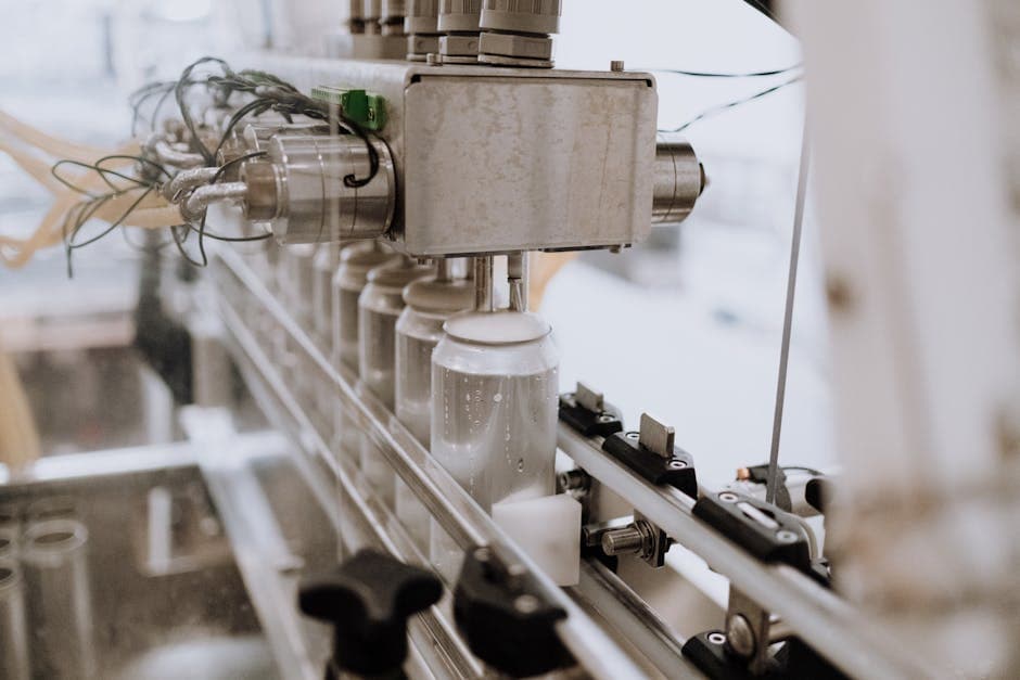
Practical guide to food and beverage automation in Australia: ISA-88 batch control, CIP, pasteurisation, hygienic design, traceability and OEE.
Key point
Process and packaging automation are different problems
Published 13 Apr 2026
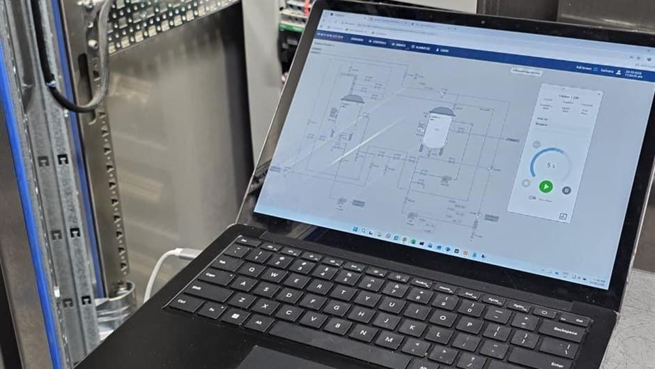
How MES and SCADA divide work in Australian food plants: ISA-95 levels, the MESA model, B2MML, contextualisation and when a dedicated MES is justified.
Key point
SCADA controls and monitors the plant; MES manages production
Published 9 May 2026
When Ignition fits an Australian food and beverage site: Perspective vs Vision, architecture and redundancy, OT security, and buying Ignition locally.
Key point
Platform fit comes before platform capability
Published 9 May 2026
Tell Metromotion Controls about the work you are planning and speak with an engineer about the next steps.