AS/NZS 61439 is the Australian and New Zealand standard for low-voltage switchgear and controlgear assemblies: the switchboards, motor control centres and control panels that sit between the supply and the plant. Most articles about it are written from the builder's side, explaining how an assembly is tested. This guide is written from the designer's side, for plant engineers and project managers who have to specify an assembly, compare builder quotes and accept the finished board.
Metromotion Controls designs switchboards, MCCs and control panels and does not fabricate them. Our switchboard and MCC design service and our control panel engineering service produce the specification and drawings that partner builders fabricate from, so the questions below are the ones we answer on every job. For the wider panel engineering picture, including form of separation, thermal design and handover records, see our guide to control panel engineering in Australia.
What AS/NZS 61439 covers
AS/NZS 61439 adopts the IEC 61439 series. It applies to low-voltage assemblies, meaning equipment rated up to 1000 V AC or 1500 V DC, and it treats the assembly as a product that has to be shown to meet its declared ratings.
The IEC series is split into parts, and the Australian adoptions follow the same numbering. Part 1 sets the general rules that apply to every assembly. Part 2 covers power switchgear and controlgear assemblies, which is where most industrial main switchboards, MCCs and larger control panels sit. Other parts cover distribution boards intended to be operated by ordinary persons, assemblies for construction sites, assemblies for public networks and busbar trunking systems. Before specifying anything, confirm which part applies, because the assembly is verified against Part 1 as modified by the relevant product part.
AS/NZS 61439 governs the assembly. AS/NZS 3000, the Wiring Rules, governs the installation it connects into: the supply cabling, protection coordination with upstream devices, earthing and the switchroom. A design has to satisfy both, and the boundary between them is one of the first things a designer should draw on the single-line diagram.
Who is responsible for what
The most useful thing the standard does for a buyer is to name the parties and their responsibilities.
- The original manufacturer is the organisation that carried out the original design of an assembly system and its design verification. This is often a switchgear or enclosure system supplier whose tested system a builder uses under licence, or a builder that has verified its own system.
- The assembly manufacturer is the organisation that takes responsibility for the completed assembly. It builds the board, stays within the limits of the verified system, carries out routine verification on each assembly and provides the documentation.
- The user is the party that specifies what the assembly must do and how it will be installed, operated and maintained.
In practice, a designer working for the asset owner acts on the user's side. The designer writes the specification, sets the ratings from the site's electrical study and process requirements, and later checks that the builder's evidence covers what was specified. That separation is deliberate. A designer who does not build the board has no reason to relax a requirement to suit a workshop, and a builder who did not write the specification cannot quietly change it.
The ratings a specification must state
The standard lists the interface characteristics the user is expected to define. If the specification is silent on one of them, the assembly manufacturer has to choose, and the choice will be the one that suits a standard product. These are the items we set in every switchboard and MCC design.
| Characteristic | What it means in practice | Where the value comes from |
|---|
| Rated voltage and frequency | The system the assembly connects to | Supply and site standard |
| Rated current of the assembly (InA) | The current the main busbar system can carry | Load list and future expansion allowance |
| Rated current of each circuit (Inc) | The current each outgoing circuit can carry continuously | Motor and load schedule |
| Rated diversity factor (RDF) | The proportion of circuit ratings expected to run at once | How the plant actually operates |
| Rated short-time withstand current (Icw) and peak withstand (Ipk) | The fault current the busbars and structure survive | Prospective fault current from the electrical study |
| Rated conditional short-circuit current (Icc) | Fault performance when protected by a specified upstream device | Protection coordination study |
| Earthing system | How the assembly relates to the installation earthing arrangement | Site electrical design |
| Degree of protection (IP) and impact protection (IK) | Resistance to dust, water and mechanical impact | Switchroom or plant-floor environment |
| Service conditions | Ambient temperature, humidity, pollution degree and altitude | Where the assembly will actually be installed |
| Form of internal separation | How busbars, functional units and terminals are divided | Maintenance and operating model |
| Access and operation | Who operates and maintains it, and whether units are fixed or withdrawable | Site maintenance practice |
Two of these deserve extra attention.
Rated diversity factor is where specifications most often go wrong. An MCC with thirty outgoing circuits rarely runs all thirty at full load, and the busbar and heat design can reflect that. On a continuous process line, however, most of the drives may run near rated load for weeks at a time. Stating the real operating pattern stops the builder assuming a diversity that the plant never achieves, which shows up later as overheating terminations and nuisance trips in summer.
Short-circuit withstand has to come from a study, not a habit. The prospective fault current at the assembly depends on the supply, the transformer and the cabling, and it changes when the network or the site transformer changes. Specifying a value below the real fault level is unsafe. Specifying one far above it adds cost to busbars, bracing and incoming devices that the site will never need.
Design verification: what the builder has to show
Design verification demonstrates that an assembly system meets the standard's requirements for its declared ratings. Under AS/NZS 61439 it can be done by testing, by comparison with a tested reference design, or by assessment against design rules, with the permitted method depending on the characteristic.
The characteristics covered include strength of materials and parts, degree of protection, clearances and creepage distances, protection against electric shock and integrity of protective circuits, incorporation of switching devices and components, internal circuits and connections, terminals for external conductors, dielectric properties, temperature rise, short-circuit withstand, electromagnetic compatibility and mechanical operation.
Temperature rise and short-circuit withstand are the two that matter most to a designer, because they are where a real board can drift away from the tested one. Calculation methods for temperature rise are only permitted within limits the standard sets, and a board with high-loss equipment such as variable speed drives, transformers or power supplies needs its heat load checked against the verified configuration. Short-circuit verification has to cover the busbar system, the connections and the protective circuit at the fault level specified.
As the designer, we do not carry out design verification; the original manufacturer and assembly manufacturer do. Our job is to ask for the evidence and check that it covers what we specified: the right rated currents, the right fault level, the form of separation we called for and the heat load the drives will produce. A verification report for a different rating, or for a configuration the builder has since changed, does not cover the board being built.
Routine verification and FAT
Routine verification is carried out by the assembly manufacturer on every assembly. It confirms that the board was built correctly: degree of protection, clearances and creepage, protective circuit continuity, correct incorporation of components, internal circuits and connections, terminals, mechanical operation, dielectric properties and the wiring, operational performance and function.
Factory acceptance testing is where the designer and the asset owner see that evidence. On a switchboard or MCC, a practical FAT covers:
- A review of the routine verification records against the drawings.
- A physical check of labelling, ratings plates, form of separation and IP-relevant details such as gland plates and door seals.
- Functional checks of control, interlock and metering circuits.
- Network checks on intelligent MCCs, where drives and motor protection devices report to the PLC.
- A walk-through of the as-built drawing set and the bill of materials.
Defects are logged, closed and retested before the board is released for delivery. The records go into the handover pack with the drawings, not into the builder's archive.
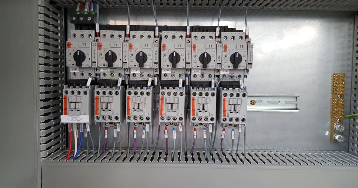
Form of separation describes how the inside of an assembly is divided between busbars, functional units and terminals, from Form 1 with no internal separation to Form 4 with each functional unit and its terminals separated from the others and from the busbars. The forms are further divided into types, and Australian specifications often add suffixes describing how busbars and terminals are insulated or housed.
The designer's task is to choose the form from the operating and maintenance model, then write the exact designation the site expects. "Form 4" on its own is not a specification. The builder needs to know which type, whether the site standard requires insulated busbars or housed terminals, and whether the requirement is that one functional unit can be worked on while its neighbours stay energised. Each step up adds barriers, space and cost, so the decision should be made once, early, and confirmed against the builder's verified system before layout.
Arc fault and personnel safety
AS/NZS 61439 addresses safety in normal operation and under specified fault conditions, but internal arcing faults need separate attention. AS/NZS 3000 contains arc fault protection requirements for larger switchboards, and many asset owners specify internal arc containment tested to IEC TR 61641 for main switchboards and large MCCs. Other measures include arc detection relays, reduced clearing times and designs that keep operators out of the arc path during normal switching.
The designer should state which approach the site requires, because it affects the enclosure construction, the switchroom layout and the protection settings. Leaving it to the builder usually produces the minimum the standard allows, which may not be what the site's safety case assumes.
The Australian context
AS/NZS 61439 is published by Standards Australia as an adoption of the IEC 61439 series, so an assembly system verified to the international standard is a sound starting point, provided any Australian variations are checked. Installation work is licensed electrical work under state regulation, which in Victoria is overseen by Energy Safe Victoria. Plant duties sit under the model WHS laws or, in Victoria, the Occupational Health and Safety Act 2004.
Site standards matter as much as the national ones. Many food, process and utility sites publish their own switchboard specifications covering preferred brands, labelling, colour, form of separation, spare capacity and documentation. A designer should work to them and flag any conflict with AS/NZS 61439 or AS/NZS 3000 before tender, not at FAT.
Common mistakes
- Specifying by brand instead of by rating. Naming a switchgear range does not tell the builder the fault level, diversity or form the plant needs.
- Copying the last job's specification. A fault level, ambient temperature or diversity factor from another site can be wrong in either direction.
- Ignoring drive heat. Variable speed drives add significant heat. An MCC verified without that load is not verified for the board being built.
- Accepting verification evidence without reading it. Check that the report covers the ratings, form and configuration actually specified.
- Treating FAT as a formality. FAT is the last point where a defect can be fixed in a workshop rather than a live switchroom.
Bringing it together
AS/NZS 61439 works best when each party does its own job. The asset owner and designer define what the assembly must do, the builder shows that its system and each board meet those ratings, and FAT and handover records prove it. When Metromotion Controls designs a switchboard or MCC, we write the specification to the standard, issue drawings partner builders can price and build from, review the builder's evidence and witness FAT, so the finished assembly matches the plant, the drives and the control system. If you are planning a switchboard, MCC or control panel project, speak with an engineer and we will come back with a scoped design approach.