1
Variable-torque loads are where the energy is
Centrifugal pumps and fans follow the affinity laws, so a modest speed reduction gives a large power reduction. Throttling valves and dampers waste that energy as pressure drop.
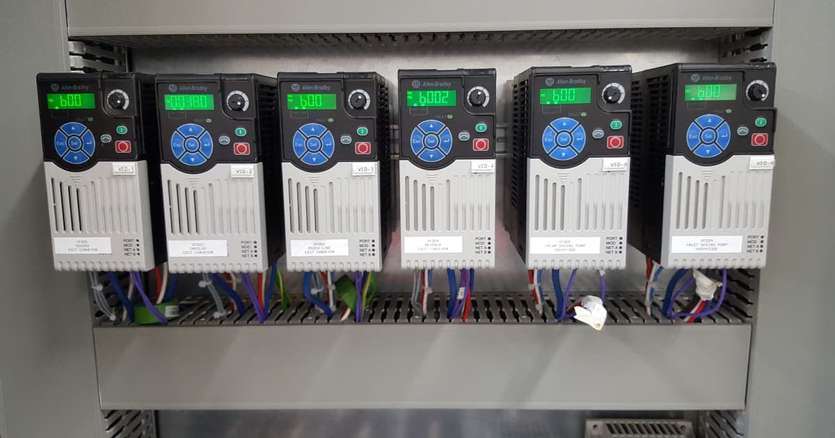
Centrifugal pumps and fans follow the affinity laws, so a modest speed reduction gives a large power reduction. Throttling valves and dampers waste that energy as pressure drop.
A pump lifting against high static head saves far less than the cube law suggests. Build the case from measured flow, hours and head, not from a brochure curve.
Motor insulation, cable length, harmonics, heat in the MCC, parameters and network integration all change when a drive is replaced. Treat it as a small engineering project, not a swap.
A variable speed drive (VSD), also called a variable frequency drive (VFD), controls motor speed by varying the frequency and voltage supplied to the motor. On the right load it cuts energy use, reduces mechanical stress and gives the control system a far better final control element than a throttling valve or damper. On the wrong load, or installed carelessly, it adds cost, heat and harmonic problems for little return.
This guide is for maintenance and engineering managers deciding where a VSD upgrade makes sense, how to build the energy case, and how to replace an ageing drive without creating new problems. It supports our automation upgrades service and our switchboard and MCC design service, where drive selection, heat and harmonics are designed into the motor control centre from the start.
Loads fall into two broad groups.
Variable-torque loads, mainly centrifugal pumps and fans, need much less power at reduced speed. These are the strongest candidates for energy savings.
Constant-torque loads, such as conveyors, positive displacement pumps, mixers, extruders and compressors of some types, need roughly the same torque across the speed range. Power falls only in proportion to speed. A VSD on these loads is usually justified by process control, soft starting or reduced mechanical wear rather than by energy alone.
The first question in any VSD project is therefore which group the load is in and whether the process actually needs to run below full flow for a meaningful share of its hours.
For centrifugal pumps and fans, the affinity laws relate speed to performance:
The cube relationship is what makes VSDs attractive. In the ideal case, running a fan at 80 percent speed needs about 51 percent of full-speed power, because 0.8 cubed is 0.512.
A throttling valve or outlet damper achieves reduced flow differently. The pump or fan keeps running at full speed and the valve burns off the excess pressure. Flow falls, but power falls only a little, and the difference becomes heat, noise, wear on the valve and, on liquid systems, a higher risk of cavitation and water hammer. Replacing that throttle with speed control is where most of the saving comes from.
The affinity laws describe the pump or fan on its own. The system it works against matters just as much.
Most fan systems and closed-loop circulation pumps work mainly against friction, so their system curve passes close to zero pressure at zero flow and the cube law is a reasonable guide.
Many process pumps are different. A pump lifting product to a tank on a mezzanine, feeding a pressurised vessel or maintaining a header pressure works against static head that does not fall with flow. As speed drops, the pump approaches the point where it can no longer overcome that head, and flow falls away quickly. The achievable saving is smaller than the cube law predicts, and there is a minimum speed below which the pump delivers little or nothing while still using energy and heating the liquid.
A sound energy case plots the real system curve, identifies the minimum useful speed and checks the pump's operating point at each duty against its best efficiency point.
Build the case from measured data wherever possible.
An illustrative example. The figures below show the method, not a client result. A 30 kW ventilation fan with outlet damper control runs 6,000 hours a year. Logging shows it spends about half its hours at around 70 percent flow and the rest at full flow. With a VSD, the reduced-flow hours need roughly a third of full-speed shaft power, because 0.7 cubed is about 0.34, rather than the high fraction a damper-controlled fan still draws. On a friction-dominated fan system that difference, spread over 3,000 hours, is a substantial share of the fan's annual energy. The same calculation on a pump with high static head could return much less, which is why the system curve has to be checked before the business case is signed off.
Many sites are not installing their first VSD but replacing a drive that has reached end of life, failed or can no longer be supported. A like-for-like swap is rarely as simple as it looks.
Three-phase electric motors are covered by minimum energy performance standards under the Greenhouse and Energy Minimum Standards (GEMS) scheme, administered through the Energy Rating program, which matters when a drive upgrade includes a motor replacement. Harmonic emissions are managed against the requirements of the local distribution network service provider and the AS/NZS 61000 electromagnetic compatibility series. Drive installation is licensed electrical work under AS/NZS 3000, and drives in switchboards and MCCs sit within assemblies designed to AS/NZS 61439, covered in our AS/NZS 61439 guide.
Supply chains are the other local factor. Replacement drives and inverter-rated motors can have long lead times, so plants with critical pumps and fans benefit from standardising on a small number of drive families and holding spares, a point that also comes up in legacy PLC migration planning.
A VSD upgrade works when it is chosen for the right load, justified with measured data and installed as a small engineering project. Pumps and fans that spend long hours at reduced flow are the best candidates. Constant-torque loads and pumps with high static head need a more careful case. Replacing an old drive is a chance to fix motor, cabling, harmonic and control problems at the same time.
Metromotion Controls designs drive and motor control scope as part of its switchboard, MCC and control panel design work, and upgrades the PLC and SCADA control around it. On the La Casa del Formaggio greenfield cheese plant, that scope covered 3 Motor Control Centres and 21 PowerFlex525 VSDs, detailed on the La Casa del Formaggio project page. If you have pumps, fans or ageing drives you want assessed, speak with an engineer.
Modernise legacy PLC, SCADA, HMI and control infrastructure with staged cutover planning.
Industrial switchboard and MCC design to AS/NZS 61439, with fabrication by partner switchboard builders.
Electrical design, control cabinet upgrades and panel-build support for industrial projects.
Process control for chemical, process and utility plants: loops, sequences, batch, boilers, steam and utilities.
Greenfield dairy facility automation with process controls and commissioning support.
A designer's guide to responsibilities, ratings, design and routine verification and FAT evidence under AS/NZS 61439.
Why most flow, pressure and level loops run PI, why slow thermal loops justify full PID with anti-windup, and a structured lambda method over trial and error.
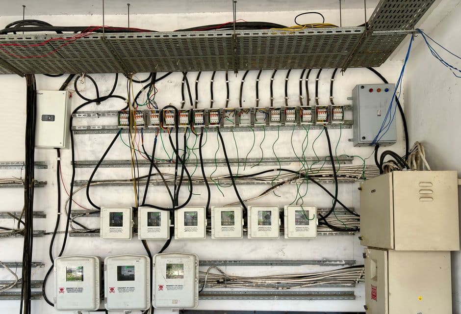
Control panel engineering in Australia: AS/NZS 61439 and AS/NZS 3000, form of separation, short-circuit rating, thermal design, FAT and handover records.
Key point
Compliance is a design input, not a final check
Published 12 Apr 2026
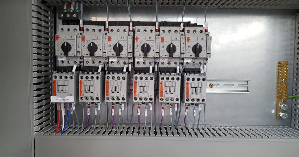
AS/NZS 61439 from the designer's side: who is responsible for what, the ratings a specification must state, design and routine verification, and FAT evidence.
Key point
The standard assigns responsibility, not just ratings
Published 25 Sept 2026
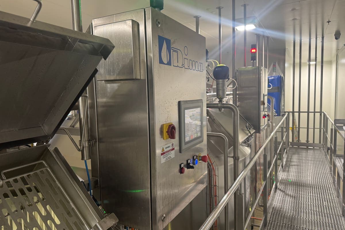
Which critical control points a food plant's control system can monitor automatically, what a CCP monitoring record must show, and how deviations, verification and data integrity are handled.
Key point
Most process CCPs are a measurement the control system already takes
Published 25 Sept 2026
Tell Metromotion Controls about the work you are planning and speak with an engineer about the next steps.